Its main characteristics are:
- 35 mm film
- lens 3 elements in " groups, 29 mm f'4
- shutter speed 1/4 to 1/250s
- sensitivity DX code 100, 200, 400 IS
- flash auto, auto-S, off, fill-in
- timer 12s
- weight 22Og with battery and 36 frames film

- In Europe this camera is named AF10 XB.
- Elsewhere in the world: Infinity XB
- In Europe this camera is named AF10 XB.
Prepare a female plug
- make the support plate as drawn
- have 3 elements of a connecting strip, step 1/10"
- stick them as shown with araldite glue
- bend the pins backward on top
prepare the connections
- prepare two ends of electric
sheet as described hereunder
- -recover a soft strip of
electronic connectors on a out of action device
-cut 2 tapes 20mm long of one electric track, 1 or 1.5mm width, if possible, in L shape
-with a razor blade,scrape off the plastic down to the electric track, until 2mm of electric track is free
- -recover a soft strip of
electronic connectors on a out of action device
- check with an electric controller that there is effective contact at each end.
- sweat at the one side scraped end a thin electric wire 70mm long and insulate it
- to the other end, scrape and make the electric track free
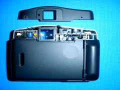
dismount the shell of the camera
- set the camera as closed
- remove the battery
- dismount the hood:
- remove two screws 4mm
long
- press the front shell, close
to the viewer, in line of viewer and flash,
meanwhile, pull the hood backwards
press on top of the front shell, right hand of the rewind place
meanwhile, shift the cover to the right, and backwards, and free it
- remove two screws 4mm
long
- dismount front shell:
- 1 is 4mm long next the
fastener
- 1 is 3mm long underneath
2 are 3mm long on battery side - 1 is 3mm long underneath
- 1 is 4mm long next the
fastener
- open the battery compartment
- separate the front shell from the body, making them sliding, and slewing them around the fastener
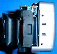
- cover with thick adhesive plate the electronic circuit above the film compartment (because of the residual voltage of the flash circuit)
- put an thin adhesive patch 5x5mm to close the hole above the film drive motor block (next to the shutter release circuit) and protect as well the motor visible gear.
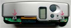
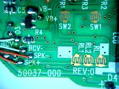
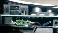
connect on the camera
- on the circuit located under
the shutter button, identify the 3 contacts:
- the common one, connected
to SPK+ (com),
- RL1 for focusing (map),
- RL2 for triggerring (obt)
- RL1 for focusing (map),
- the common one, connected
to SPK+ (com),
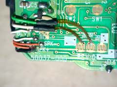
- sweat the free ends of the 2
bands on the edge of the contact tracks RL1 and RL2
- for that, first sweat
the end of electric track on the band, then place it
on the edge of circuit, now heat with soldering-bit
just enough (Do not damage center of contact tracks,
otherwise shutter button may not work properly)
OBT is on RL2; MAP is on RL1
- for that, first sweat
the end of electric track on the band, then place it
on the edge of circuit, now heat with soldering-bit
just enough (Do not damage center of contact tracks,
otherwise shutter button may not work properly)
- flat well the two bands over the camera circuit
- sweat the wire COM on the spot shown SPK+
- run the wires under this circuit
- sweat wires on the plug, com in center (Humez's type connector)
Mount the front shell
- withdraw the adhesive tape
- flow the parts with dry air
- set back the front shell proceeding as reverse way, and paying attention to the passage of flash buttons and timer when sliding over the shutter connections
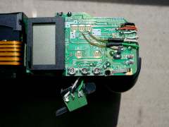
Fix the plug
- cut the small boss which impede the correct setting of the left part of the plug support
- with araldite, or other strong glue stick the plug on the top of the film drive motor; well adjust its position with regards to the top hood
- locate and draw on the hood
the spot of the 3 holes for the male connector to go through:
- My tip: have a transparent plastic sheet drilled with the 3 holes, set it on the plug, with the male plug in; fix it on the back with adhesive tape; remove male plug; set the hood; mark the 3 holes location.
- drill one hole dia 1,5mm in the hood, and check its alignment with the plug
- drill the other holes (I use a template) and check that the 3 pins of the male plug insert freely
test the camera and complete assembly
- put the battery back, and check the camera functions
- put the male plug in and check the connexion works properly (see hereunder)
- If everything is OK, set the hood, and all the screws.
