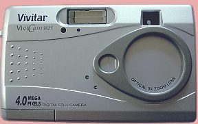
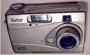
Specifications
- sensor CCD 4,0 Megapixels
- resolutions 2272x1704, 1600x1200
- lens zoom 7.25 to 20.3 mm, aperture
2.9 to 4,8 mp angular field 52° to 20°
- macro from 10 to 70cm (4"
to 28")
- autofocus, or manual on infinity
- AE exposure mode with highest speeds
- SD memory card
- weight 210g with batteries
- 2 AA batteries , consumption 570mA
without screen and 750mA with screen.
- image numbering: Imag0001 which is reset to each full delete of images
in the card.
- price: 260 euros spring 2004
|
|
The
images got are excellent, well exposed, having a good saturation
of colors, rather neutral, with blue atmosphere, like postcards,
and a fairly nice contrast, not exaggerated. The result is outstanding
for a camera of this price.
For all the technical
details, and read the instruction manual, go to the web site
Vivitar.com
The auto shut-off function
can be programmed to 5mn maximum. When activating another function,
like pre-exposure, reset the auto shut-off. Hopefully, it is
quite easy to connect electrically the functions on/off, auto
exposure lock, and shutter. |
|
|
The
installation of a shutter plug on the vivicam 3825 is quite
easy.
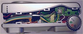
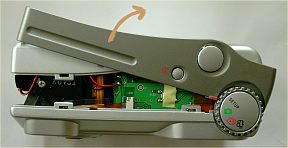
Dismounting
Remove batteries and memory card
Remove these screws: 1 (5mm) aside
the video plug; 1 (5mm) aside the strap ring; 1 (6mm) aside
the battery compartment. It is not necessary to remove
others.
Take away the center cover, starting
from the video plug side, push it upwards; smoothly push
away a little bit the rear cover from the top; then move
the cover around the select mode knob.
|
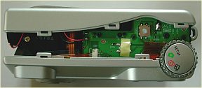
Install the plug
remove the beeper under the front
cover, next to the viewfinder.
prepare a female plug bar of 5
pins, 2.5mm step, which will be placed in the front cover,
behind the small bulkhead which holds the beeper.
find the right way to put it in
place.
with the male plug, draw the location
of the holes, and drill Ø0.8mm or 1mm. With 5 pins,
there is one at the edge of the cover. I shifted all a little
and get the side one in the center cover.
prepare 5 tiny electric wires,
10 cm long each, and solder on the female plug. Well log
them.
Insulate this plug with 2 components
putty. set the wires such as the volume us as small as possible.
Set the female plug in its location;
use the male plug to center it through the holes, and maintain
it. Use 2 components putty to fix it, or quick-setting araldite
bound.
Watch not to get araldite leak
in the plug connectors, so hold the camera and turn
it on sides where it will not pour the wrong way.
|
|

The number of pins of the plug is from
2 to 5, depending on the functions you want to have remote control. |
-
The f.e.s. function is pre-setting
focus and exposure.
When B2 and B1 are connected directly,
the camera first activate the focus, and the exposure, and
trigger the shutter afterwards. A short contact between
B1 and B2 is equal to the f.e.s. function and don't trigger
the shutter!
|
|
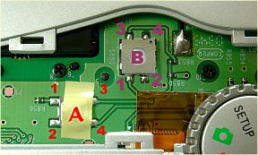
Where to connect?
- Switch A: on/off
- the two lines are A1, A3 and A2, A4
- There is contact and either switch-on, or switch-off
when there is connexion between: A1-A2, or A3-A4, or A1-A4,
or A2-A3.
-
- Switch B: shutter
- B1 = shot (shutter release)
- B2 = common
- B3 = f.e.s ( focus and exposure settings)
- B4 = not used
- Nota: wiring B1 and B2 only is
sufficient for f.e.s. and shot fonctions.
|
-
-
-
|
|
Connect on the switches
- arrange the wires, and cut them to length up to the
switches
- bare the ends of the wires, and tin these ends
- solder the wires on the switches
|
Remounting
- put back the beeper
- set the wires not to impede to place back the cover.
If necessary use some adhesive to maintain them.
- before to close, it is possible to test the camera:
- load the batteries, the memory card, and test.
- if OK, put back the central cover, starting on the select
mode knob
- put back the screws
|
|
 |