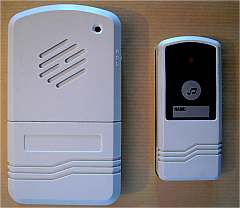
There are wireless house bell which
are a small radio emitter and a receiver with a bell. We
have found a cheap one, which frequency is 433,92
MHZ, which works on coded signal, and which range is given
100m. .Such specification makes it a possible tool to trigger
the shutter release of a camera.
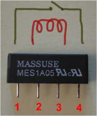
The modification is simple, and
only needs a relay SIL REED, available in the electronic
components.
On the cradle, I have confirmed
the effective release at 100m, and irregular release up
to 150m.
A round model with 150m range has
a 170mm antenna in the receiver. The shape is not practical,
and the crescent electronic board is not easy to replace
in another box.
|
|
-
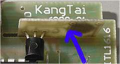
The maker of this wireless house
bell is Kangtai. It is distributed in France under the trade
mark Kangtai and by the company GEFOM www.gefom.com under the trade mark
Gefolec. But there is also a round shape receiver under
the trade mark PT with a given range of 150m. |
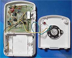
DISMOUNTING
On the back take away the plastic
handle.
Remove the two screws
Open the battery compartment
Take out the cover
On the speaker, unsolder the wire
connected to the circuit board, and the led.
Remove the speaker, and the battery
connector linked to it.
Remove the screw on the circuit
board
Take out the circuit board
|
|
 |
|
|
REMOVE THE BELL CIRCUIT
-
|
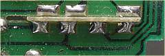
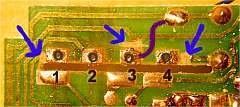
SETTING THE RELAY
The relay is referenced SIL REED
1T
At the place of the former bell
circuit, drill 4 holes Ø0.5mm lined up, 2,5mm step
(start drilling on the circuit side of the board)
By grinding, cut the circuit tracks
near the drilled holes 1, 3 and 4.
Set and solder the relay ( there
is no direction)
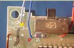
With a thin electric wire, link
the eye 3 to the minus
Solder two wires on the eyes 1
and 4 and connect them on the release connector. See Connexion |
|
|
-
-
|
|
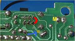
RE-CONNECT THE LED
The led is re-used as "on" indicator
Link the two last pins of the switch
(red line)
Add a ground wire and solder it
at M
Grind the circuit track at the
place shown with blue arrow.
Connect the led to this wire and
to the wire linked to P (if the
led would not light, invert the connections)
Put the led on the cover, and maintain
it with adhesive tape or with a drop of glue.
|
MODIFY the BATTERIES
Cut the small wall holding the
batteries (leave the second one which will be used to press
the battery against the springs)
Replace the flat connector by the
short one with a spring
Unsolder the ground (minus) wire
on this connector (this wire is linked to GND on the circuit)
and solder it on the long connector. Remove some plastic
wall to pass the wire.
Remove the long connector on the
opposite side
Unsolder from this connector the
"plus" wire (linked to VCC on the circuit) and
solder it on the short spring connector.
Install an unmistaking boss
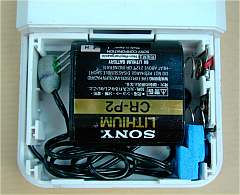
Set a battery CR-P2 and adjust
the springs to make good connexion with the battery.
|
|
For a good work of the relay, the
circuit must be fed with 6Volts. A lithium battery CR-P2
is used. 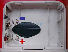 This unmistaking boss has been
done with 2 components compound, and moulding the battery
shape.
|
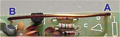
The end A is active; the B end can be let
free. |
|
CHANGE THE ANTENNA
- It's not mandatory, but it increases the range
to 150m.
Prepare a wire Ø1mm or more,
170mm long
Remove the existing antenna wire
AB
solder the new wire at place shown
A
|
RE-ASSEMBLY
Run the release chord until the
battery compartment
Close the hole let by the handle.
Put back the circuit board and
screw it
Mount the cover and screw it
Place the battery 6V
Test it
Note arrangement
of release chord during transportation.
|
|
 |