Technique
The servo is dismounted as for a full rotation
pan servo. It is possible to remove the potentiometer outside
and set it on the tilt pivot.
On a normal 35x40x20mm servo,
next to the motor, there is enough space to drill a hole Ø2mm.
It must be exactly perpendicular. Then, insert a Ø2mm
rod, 25mm long, screwed at each end, and fix it on the cradle.
On the outside spindle of the servo the hole for the screw is
re-tapped for a normal Ø3mm screw. It will maintain the
worm.
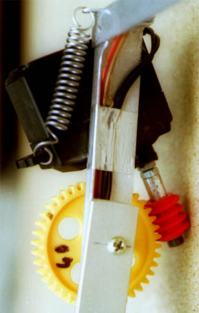
On the tilt pivot, fix a cog-wheel. Donĺt forget the
spiral spring between the servo and the rig, which holds tight
the worm to the cog-wheel.
Iĺm using cog-wheels Ø32mm
with 30 cogs or Ø40mm with 40 cogs, both 6mm width. The
worm screw is Ø12mm with archimedean shape, 4mm step.
|
|
- Old facts
Having rigs with video control (even if it
usually donĺt work well), I was not satisfied with the tilt
movement. It was set as direct drive on the tilt servo, and
I found it was too sudden and not enough precise.
Since
years I had the idea to change it for a worm system. On my portrait-frame
rig I have experienced a cog-wheel with a 1:2 ratio which I
found as short improvement.
End of 1998, after some
unsatisfying sessions of KAP, I was determined to action and
to mount the worm screw that I had purchased years ago. So I
designed and re-designed until I got a simple and easy installation
giving the efficiency I was expecting.
I have now mounted
about a dozen on different rigs, including frame change and
with mini-servos. After so many seasons using them I can guarantee
it is the best tilt system I ever used.
-
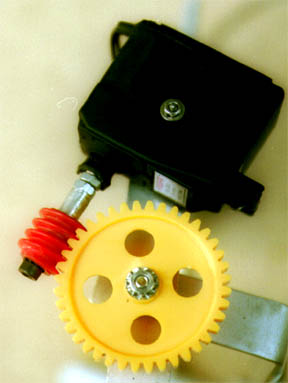
This is gear-wheels
Ø32 with 30 teeth, and Ø40 with 40 teeth,
both 6mm thick. the cog-wheel is Ø12mm with a 4mm
step.
With longer
cog-wheel, enlarge the hole at one end to fit tight over
the servo gear.
|